Features:
> 5.7-inch color touch screen, front panel operation
Naming convention: Taking TIS 100C06 as an example
TIS : Automotive Transient Pulse Conducted Interference Signal Simulator
100 :Maximum voltage 1000V;
C : Representing Current
06 :Output current level, 06:60A 10: Output voltage level 100A
Naming convention:
|
Technical Parameter |
||
|
Micro pulse generator module P1 |
||
|
Test Voltage |
3 - 600 V |
|
|
Polarity |
Negative |
|
|
Rise time Tr |
0.5 μs – 1 μs |
|
|
1.5 μs – 3 μs No load |
||
|
Duration Td |
50 μs 土20% No load |
|
|
Source impedance |
2 Ω,4 Ω,10 Ω,20 Ω,30 Ω,50 Ω |
|
|
Test frequency |
1 - 9999 |
|
|
DUT voltage monitoring |
10 : 1 |
|
|
DUT current monitoring |
10 A : 1 V |
|
|
Pulse interval |
0.2 s -999 s (with the minimum interval depending on the output voltage) |
|
|
Micro pulse generator module P2a |
||
|
Test voltage |
3 - 200 V |
|
|
Polarity |
W4 CI/GI |
|
|
Rise time Tr |
0.5 μs – 1 μs |
|
|
Duration Td |
50 μs 土20% No Load |
|
|
Source impedance |
2 Ω,4 Ω,10 Ω,20 Ω,30 Ω,50 Ω |
|
|
Test frequency |
1 - 9999 |
|
|
DUT voltage monitoring |
10 : 1 |
|
|
DUT current monitoring |
10 A : 1 V |
|
|
Pulse interval |
0.2 s -999 s (with the minimum interval depending on the output voltage) |
|
|
COUPLING |
ICC, DCC |
|
|
Electric fast transient/pulse train generator module P3a/3b |
||
|
Test voltage |
18-1000 V |
|
|
Polarity |
Pulse 3b is positive, pulse 3a is negative |
|
|
Rise time Tr |
5 ns土30% 50 ohm Load |
|
|
Duration Td |
150 ns - 45/+45 ns 50 ohm Load |
|
|
Source impedance |
50 Ω |
|
|
Number of pulses |
1 - 200 |
|
|
Pulse group interval time |
50 ms - 999 ms |
|
|
Pulse frequency |
0.1 kHz - 200 kHz |
|
|
Test duration |
1 s - 50000 s |
|
|
Coupling method |
CCC,DCC |
|
|
Output method |
Source port output |
BNC |
|
Power port output |
Coaxial terminals |
|
|
General parameters |
||
|
Supply voltage |
AC 110/220 V,Soil 10%,45-65 Hz |
|
|
Environmental temperature |
15 - 35 ℃ |
|
|
Relative temperature |
35% -85% RH (no condensation) |
|
|
External dimensions |
TIS 100C06 Output current 60 A,4U chassis |
TIS 100C10 Output current 100 A, 6U chassis |
|
Weight |
TIS 100C06 About 20 kg |
TIS 100C10 About 20 kg |
|
Trigger method |
Automatic trigger, manual trigger, external trigger |
|
|
Network |
Built in coupling/decoupling network 60 V/60 A |
|
|
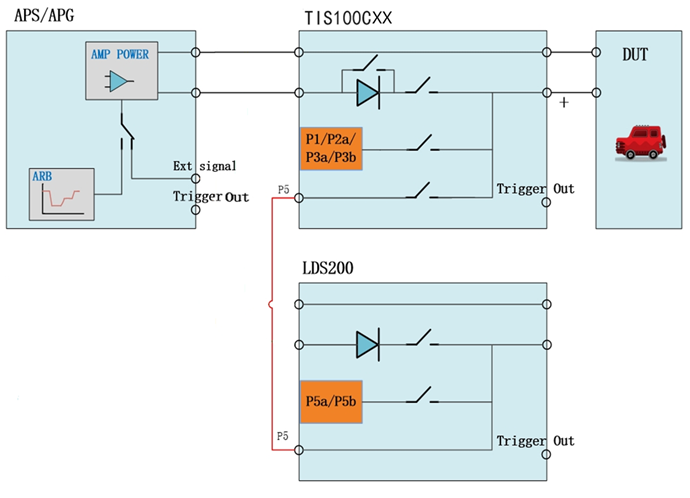
Input |
Power supply for the tested equipment |
DC voltage input from APS or APG or other DC power sources |
|
Pulse 5,7 |
Overlay pulse 5 and pulse 7 through the TIS100C06 network |
|
|
Output |
Output from LDS200 input |
Central test equipment output port |
|
Coaxial output port |
Connect capacitive coupling clamps that meet the requirements of ISO7637-3 standard |
|
|
Standard accessories |
||
|
One host, instruction manual, testing report, quality assurance certificate, testing line, power line, DUT power line, grounding wire |
||
|
Optional accessories |
||
|
ISO 7637-3 Calibration Attachment |
||
|
1. Current injection BCIP7637-3
|
Frequency range: 4 kHz -100 MHz |
|
|
2. Calibration fixture BCICF-400
|
Frequency range: DC - 400 MHz |
|
|
Characteristic impedance: 50 Ω |
||
|
3. Direct capacitance coupling DOC-100 nF
|
Capacity: 100 nF |
|
|
Voltage withstand value: 200 V |
||
|
4. Direct capacitance DOC-100pF
|
Capacity: 100 pF |
|
|
Voltage withstand value: 200 V |
||
|
5. Capacitive coupling clamp V-EFTC
|
Coupling capacitance:100 pF - 200 pF DC 5 kV |
|
|
ISO 7637-2 Calibration Attachment |
||
|
6. Calibrate the resistance PVK
|
Model |
Impedance [Ω] |
|
PVK 05 |
0.5 |
|
|
PVK 1 |
1 |
|
|
PVK 2 |
2 |
|
|
PVK 4 |
4 |
|
|
PVK 10 |
10 |
|
|
PVK 20 |
20 |
|
|
PVK 30 |
30 |
|
|
PVK 50 |
50 |
|
|
Other Accessory |
||
|
7. Software |
The computer online control software AutoLab supports Windows 7 and above. It is easy to use, has a beautiful and intuitive user interface, and various operational functions and standard testing libraries allow users to easily complete custom testing programs; |
|
|
It can automatically/manually identify the connected AutoLab testing equipment and perform automatic configuration; The template based reporting feature can help users generate test reports flexibly. |
||