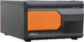
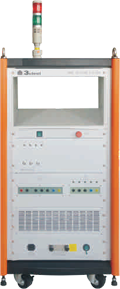
CCS 800 is an intelligent multifunctional combined immunity testing (EMS) equipment that can meet various testing requirements for transient pulses, surges, communications, voltage drops, ringing waves, pulse magnetic fields, and power frequency magnetic fields according to international standards and product series standards. The maximum testing voltage can reach 8kV.
CCS 800 is the best choice for fully compatible immunity testing solutions. Meets the anti-interference testing requirements of EU CE certification and CCC certification for single-phase test equipment, with a built-in fully automatic single-phase coupling/decoupling network, and can also perform three-phase five wire test equipment testing through an automatically controlled external coupling/decoupling network (up to 400A). We provide you with various testing accessories to meet various application needs such as power frequency magnetic field testing
Features
> 5.7-inch color touch screen front panel operation;
> Surge failure detection function;
> Surge voltage and current measurement and acquisition;
> Test the orchestration function;
> Built in multifunctional testing module combination;
> Built in fully automatic single-phase coupling/decoupling network AC 300V 20A/32A,
DC 300V 20A/32A;
> Can control external three-phase coupling/decoupling network and other
functional modules;
> Ethernet and RJ45 interfaces, used for PC remote control and printing test reports.
|
General Parameters |
|
|
Display |
5.7-inch TFT touch screen |
|
Scope of Working Power Supply |
100 ~ 264 V AC, 47 ~ 63 Hz |
|
Fuse |
6 A |
|
Maximum Power Consumption |
300 W |
|
Communication Method |
Ethernet LAN |
|
External Control Mode |
25 needle parallel thread |
|
External Trigger Input |
BNC, 5V TTL |
|
CRO Triggers Output |
BNC, 5V TTL |
|
Operation Control Input |
BNC, 5V TTL |
|
Pulse Triggering Method |
Manual, automatic, externally triggered |
|
External Synchronous Input |
20 ~ 400 V, 45 ~ 65 Hz |
|
Warning Light Output |
Multi core connector output, matched with external alarm light module (optional) |
|
Safety Circuit |
Short circuit of safety loop, stop working when the safety loop is open circuit |
|
Failure Detection |
When it fails, the front panel LCD displays and interrupts the instrument's operation |
|
Instrument Working Status Indication |
LED indication, LCD display |
|
Instrument Grounding Connection Method |
Use a flat grounding wire |
|
Chassis Size |
19 inches/8U L * W * H: 650 * 445 * 371 mm |
|
Instrument Weight |
About 65 kg |
|
Environmental Scope |
15℃ ~ 35℃ |
|
Pressure Range |
86 kPa ~ 106 kPa |
|
Humidity Range |
45% ~ 75% |
|
Built in coupling/decoupling network (single-phase fully automatic) |
|
|
EUT Carrying Capacity |
AC 300 V 20 A/32 A (optional) 50/60 Hz |
|
DC 300 V 20 A/32 A (optional) |
|
|
EUT Power Input and Output |
4mm banana plug cable |
|
EUT Voltage Monitoring Output |
BNC output, 100V: 1V |
|
EUT Current Monitoring Output |
BNC output, 10 A: 1 V |
|
Synchronization Method |
Internal synchronization, external synchronization, asynchronous |
|
Internal Synchronization |
0 °~360 °, 1 ° step setting or random mode |
|
Pulse group Coupling/decoupling |
Built in single-phase automatic coupling/decoupling network |
|
1.2/50 μs Combined Wave Coupling/ decoupling |
Built in single-phase automatic coupling/decoupling network |
|
Ringing Wave Coupling/decoupling |
Built in single-phase automatic coupling/decoupling network |
|
IEC-61000-4-4 Electrical Fast Transient Pulse Test |
|
|
Source Port Test Voltage Range |
0.25 kV ~ 6 kV (±10%) |
|
Network Port Test Voltage Range |
0.25 kV ~ 5.5 kV (±10%) |
|
50 Ω Calibration Waveform |
5 ± 1.5 ns, 50 ns ± 15 ns |
|
1000 Ω Calibration Waveform |
5 ± 1.5 ns, 50 ns(- 15 / + 100 ns) |
|
Pulse Frequency |
0.1 kHz ~ 1000 kHz |
|
Pulse Group Period |
11 ms ~ 9999 ms |
|
Pulse Train Duration |
0.075 ms ~ 750 ms |
|
Experimental Mode |
Optional scheduling mode |
|
Polarity |
Positive, negative, first positive and then negative |
|
Coupling Capacitor |
33 nF |
|
IEC-61000-4-5 Surge Immunity Test |
|
|
Test Voltage |
0.25 kV ~ 8 kV (±10%) |
|
Test Current |
0.125 kA ~ 4 kA ± 10% |
|
Voltage Waveform |
1.2 μs ± 30% , 50 μs ± 20% |
|
Current Waveform |
8 μs ± 20%, 20 μs ± 20% |
|
Output Impedance |
2 Ω, 12 Ω |
|
Test Interval Time |
6 ~ 99 s (the shortest depends on the test voltage) |
|
Number of Experiments |
1~999 times |
|
Experimental Mode |
Optional scheduling mode |
|
Polarity |
Positive, negative, first positive and then negative |
|
Calibration Capacitor |
18 μF built-in |
|
Coupling Resistance |
0 Ω, 10 Ω |
|
Coupling Capacitor |
Built in at 9 μF and 18 μF |
|
Surge Voltage Peak Detection |
LCD display, BNC output 1000V: 1V |
|
Surge Current Peak Detection |
LCD display, BNC output 500A: 1 V |
|
IEC-61000-4-5 Communication Wave Test |
|
|
Test Voltage |
0.25 kV ~ 8 kV (±10%) |
|
Test Current |
6.25 A ~ 200 A ±10% |
|
Voltage Waveform |
10 μs ± 30% , 700 μs ±20% |
|
Current Waveform |
5 μs ± 20%, 320 μs ±20% |
|
Output Impedance |
15 Ω, 40 Ω |
|
Test Interval Time |
6 ~ 99 s (the shortest depends on the test voltage) |
|
Number of Experiments |
1~999 times |
|
Experimental Mode |
Optional scheduling mode |
|
Polarity |
Positive, negative, first positive and then negative |
|
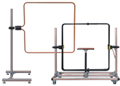
IEC-61000-4-8 Power Frequency Magnetic Field Test |
|
|
Module |
MFT series |
|
Magnetic Field Intensity |
TCXS 111 single turn magnetic field coil |
|
1 A/m~100 A/m (continuous) 100 A/m~400 A/m (1 s~10 s short-term) |
|
|
TCXS 113 three turn magnetic field coil: |
|
|
1 A/m~300 A/m (continuous) 300 A/m~1200 A/m (1~10s short-term) |
|
|
Current Waveform |
50 Hz/60 Hz sine wave |
|
Current Distortion Rate |
< 5% |
|
Generator Output Current |
1 A ~ 450 A |
|
Waveform Interval Time |
1 s ~ 9999 s |
|
Test Duration |
1 s ~ 28800 s |
|
Magnetic Field Coil Size |
1 m x 1 m, other |
|
Shape of Magnetic Field Coil |
Rectangle, Other |
|
Output Magnetic Field Strength |
Scheduling Settings |
|
IEC-61000-4-9 Pulse Magnetic Field Test |
|
|
Magnetic Field Strength (1*1 m coil) |
100 A/m ~ 1200 A/m |
|
magnetic Field Strength (1*2.6 m coil) |
100 A/m ~ 880 A/m |
|
Coil Waveform (1*1 m Single Turn) |
8 μs(+ 2.4 μs /- 0.8 μs),20 μs(+ 6 μs/-2 μs) |
|
Coil Waveform (1*2.6 m Single Turn) |
8 μs(+ 3.2 μs/- 0.8 μs),20 μs( + 8 μs/ -2 μs) |
|
7 ~ 99 s |
|
|
Test Interval Time |
1~999 times |
|
Number of Experiments |
Optional scheduling mode |
|
Experimental Mode |
Positive, negative, first positive and then negative |
|
Polarity |
1 m x 1 m, other |
|
Magnetic Field Coil Size |
Rectangle, Other |
|
Shape of Magnetic Field Coil |
100 A/m ~ 1200 A/m |
|
IEC-61000-4-11&IEC-61000-4-29 Cycle Drop Test |
|
|
Module |
VVT series |
|
EUT Carrying Capacity |
AC 300 V 20 A/32 A (optional) 50/60 Hz |
|
DC 100~300 V 20 A/32 A (optional) |
|
|
EUT Voltage Frequency |
45 ~ 65 Hz |
|
100 Ω Calibration Waveform (Communication Loss) |
1 ~ 5 s |
|
100 Ω Calibration Waveform (DC Drop) |
1 ~ 50 s |
|
Impulse Current |
500 A |
|
Interrupt Level |
0% |
|
Temporary Voltage Drop |
0%~100% (applicable to attachment VVT/VMT series) |
|
Duration of Temporary Descent and Interruption |
0.3~9999 cycles or 1ms~9999ms |
|
Temporary Reduction and Interruption Interval Time |
50 ms ~ 50000 ms |
|
Temporary Reduction and Interruption of Test Frequency |
1 ~ 9999 times |
|
Temporary Descent, Interruption of Ascent, Descent time |
1~5 μs (100 Ω load) |
|
IEC-61000-4-12 Ringing Wave Test |
|
|
Open Circuit Output Voltage (PK1) |
0.25 kV ~ 8 kV ±10% |
|
Open Circuit Voltage Oscillation Frequency (1/T) |
100 kHz ±10% |
|
Before the Waveform of Open Circuit Voltage(T1,10%-90%) |
PK1 0.5 μs ± 30% |
|
Open Circuit Voltage Decay Rate |
40%<(PK2)/(PK1)<110%, 40%<(PK3)/(PK2)<80% |
|
40% <(PK4)/(PK3)< 80% |
|
|
Short Circuit Current Wave Front (T2, 10% -90%) |
0.2 μs ≤ Pk1 ≤ 1 μs |
|
Open Circuit Voltage (PK1) 8000 V When, Short-circuit Current (P1) |
666 A ± 10% at 12 Ω; 266 A ± 10% at 30 Ω |
|
Output Impedance |
12 Ω, 30 Ω |
|
Test Interval Time |
6 ~ 99 s |
|
Pulse Frequency |
1~999 times |
|
Experimental Mode |
Optional scheduling mode |
|
Polarity |
Positive, negative, first positive and then negative |
|
CCS 800 Selection Guide List |
|||||||||
|
Host |
Compact Immunity Test System CCS 800 |
IEC 61000 |
CDN single-phase three wire network |
||||||
|
- 4 - 4 |
- 4 - 5 |
- 4 - 8 |
- 4 - 9 |
- 4 - 11 |
- 4 - 12 |
- 4 - 29 |
|||
|
√ |
√ |
|
√ |
√ |
√ |
√ |
√ |
||
|
Optional module |
|||||||||
|
|
Power frequency magnetic field module MFT 400 / 1200 |
|
|
√ |
|
|
|
|
|
|
|
AC power supply temporary drop, short-term interruption, voltage change module VVT 2216S / SV |
|
|
|
|
√ |
|
|
|
|
|
Power failure and power frequency magnetic field module VMT 2216S / SV |
|
|
√ |
|
√ |
|
|
|
|
|
Pulse group coupling/ Decoupling network EFTN xxxxT series |
√ |
|
|
|
|
|
|
Can root according to EUT electric Pressure the electric flow etc. level want seek set system |
|
|
Lightning surge coupling/ Decoupling network SPN xxxxT10 series |
|
√ |
|
|
|
√ |
|
|
|
|
Surge and group pulse coupling/ decoupling network SEPN xxxxT10 series |
√ |
√ |
|
|
|
√ |
|
|
|
|
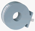
Magnetic field coil TCXS series |
|
|
√ |
√ |
|
|
|
|
|
|
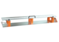
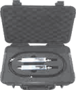
Capacitive coupling clamp
|
√ |
|
|
|
|
|
|
|
|
Note: If only the host is selected and VVT or VMT testing modules are not available, an additional power supply is required for IEC 61000-4-11/29 testing |
|||||||||
|
List of Testing and Measurement Selection Guidelines |
||||||||
|
Instrument name and model |
IEC 61000 |
|||||||
|
- 4 - 4 |
- 4 - 5 |
- 4 - 8 |
- 4 - 9 |
- 4 - 11 |
- 4 - 12 |
- 4 - 29 |
||
|
|
High voltage differential probe VCF 80 |
|
√ |
|
|
√ |
√ |
√ |
|
|
Broadband current monitoring clamp CM 0220M |
|
√ |
|
√ |
|
√ |
|
|
|
10 kV surge calibration module CCM 1000 |
|
√ |
|
|
|
|
|
|
|
EFT pulse train generator calibration device TFB 500 / 1000 |
√ |
|
|
|
|
|
|
|
|
Immunity testing software CoreLab |
√ |
√ |
√ |
√ |
√ |
√ |
√ |