|
Technical Parameters |
|
|
Coupling Mode |
Cable Induction |
|
Rise Time |
< 100 ns |
|
Duration |
|
|
Test Level for Single Stroke Tests |
|
|
Test Level for Multiple Stroke Tests |
50 V ~ 2000 V (first wave, -0% ~ +20%) |
|
25 V ~ 1000 V (subsequent wave, -0% ~ +50%) |
|
|
Polarity |
Positive,negative |
|
Coupling Transformer |
LVT-2 |
|
Voltage W3-1MHz-H Signal Pins & Power Pins Injection Tests |
|
|
Coupling Mode |
Pin Injection |
|
Output Impedance |
25 Ω |
|
Frequency |
|
|
Decay Rate of 5th Waveshape |
25% ~ 75% of the first wave |
|
Test Level for Single Stroke Tests |
|
|
4 A ~ 180 A (short-circuit current,-0%~+10%) |
|
|
Polarity |
Positive,negative |
|
Phase Sync |
0°~ 359°, resolution 1° |
|
EUT Maximum AC voltage |
230 V |
|
EUT Maximum Power Supply Frequency |
800 Hz |
|
EUT Maximum DC Voltage |
±50 V |
|
Voltage W3-1MHz Cable Bundle Cable Induction Tests |
|
|
Coupling Mode |
Cable Induction |
|
Frequency |
1 MHz ± 20% |
|
Decay Rate of 5th Waveshape |
25% ~ 75% of the first wave |
|
Test Level for Single Stroke Tests |
50 V ~ 4500 V(-0% ~ +20%) |
|
Test Level for Multiple Stroke Tests |
50 V ~ 4500 V (first wave, -0% ~ +20%) |
|
50 V ~ 2250 V (subsequent wave, -0% ~ +50%) |
|
|
Polarity |
Positive,negative |
|
Coupling Transformer |
LVT-2 |
|
Voltage W3-1MHz-MB Cable Bundle Cable Induction Multiple Burst |
|
|
Coupling Mode |
Cable Induction |
|
Frequency |
1 MHz ± 20% |
|
Test Level for Single Stroke Tests |
60 V ~ 1920 V(-0% ~ +20%) |
|
Decay Rate of 5th Waveshape |
25% ~ 75% of the first wave |
|
Output Impedance |
≥60 Ω |
|
Coupling Transformer |
LVT-2 |
|
Voltage Waveform 3 (10 MHz) Cable Bundle Cable Induction Tests |
|
|
Coupling Mode |
Cable Induction |
|
Frequency |
10 MHz ± 20% |
|
Decay Rate of 5th Waveshape |
25% ~ 75% of the first wave |
|
Test Level for Single Stroke Tests |
50 V ~ 4000 V(-0% ~ +20%) |
|
Test Level for Multiple Stroke Tests |
50 V ~ 4000 V (first wave, -0% ~ +20%) |
|
50 V ~ 2000 V (subsequent wave, -0% ~ +50%) |
|
|
Polarity |
Positive,negative |
|
Coupling Transformer |
LVT-2 |
|
Current W6 Cable Bundle Cable Induction Tests |
|
|
Coupling Mode |
Cable Induction |
|
Current Range |
5 A ~ 160 A |
|
Rise Time |
0.25 μs ± 20% |
|
Duration |
4 μs ± 20% |
|
Coupling Transformer |
LVT-3 |
|
General Parameters |
|
|
Display Screen |
5.7-inch TFT touch screen |
|
Working Power |
AC 220 V ± 10%,50/60 Hz |
|
Fuses |
6A |
|
Maximum Power Consumption |
200 W |
|
Memory Space |
Infinite (PC) |
|
Communication Methods |
Ethernet LAN, RJ45 |
|
Working Status Indication |
Front panel LED indication, LCD display |
|
Grounding Connection Method |
Use a flat grounding wire |
|
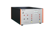
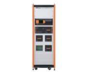
Dimension |
ETS 160MB/4U 450 mm(W)*190 mm(H)* 620 mm(D) |
|
ETS 160ML/4U 450 mm(W)*190 mm(H)* 550 mm(D) |
|
|
Weight |
Two hosts weighing a total of 37 kg |
|
Ambient Temperature |
15℃ ~ 35℃ |
|
Relative Humidity |
45% ~ 75% ,RH(no condensation) |
|
Atmospheric Pressure |
86 kPa ~ 106 kPa |
|
Standard Accessories |
|||
|
Power Cord, Instruction Manual, Flat Grounding Wire, Fuse, RF Cable, Calibration Report, Test Line, Product Warranty Certificate |
|||
|
Optional Accessories |
|||
|
1 |
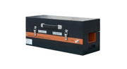
Coupling Transformer |
Model: LVT-2 |
|
|
2 |
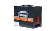
Coupling Transformer |
Model: LVT-3 |
|
|
3 |
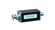
Power Blocking Device |
Model: CN-2 |
|
|
4 |
Decoupling Network |
Model: DN 6020T |
|
|
5 |
Decoupling Network |
Model: DN 8020T |
|
|
6 |
Decap Cell |
Model: DN-4200T |
|
|
7 |
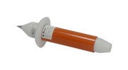
Handheld Pin Injection Probe |
Model: HIP 5000 |
|
|
8 |
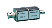
Current Divider |
Model: MCS 01 |
|
|
9 |
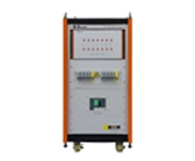
35U Rack |
Model: ETS 160MB-35U |
|
|
10 |
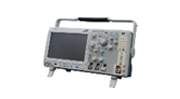
Digital Oscilloscope |
Model: MDO3012 |
|
|
11 |
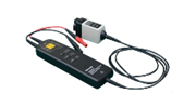
Differential Probe |
Model: THDP0100(Tektronix) |
|
|
12 |
Wide-band Current Monitor |
Model: CM 0103M |
|
|
13 |
Immunity Testing Software |
Model: Corelab |
|