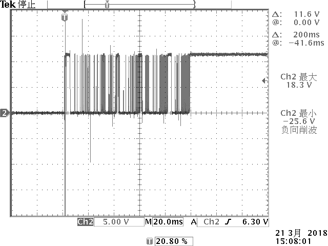
Waveforms:
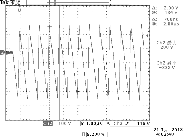
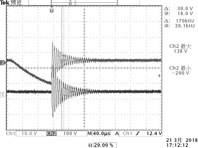
CI 220, Pulse A1, Mode 1
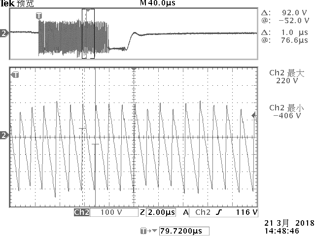
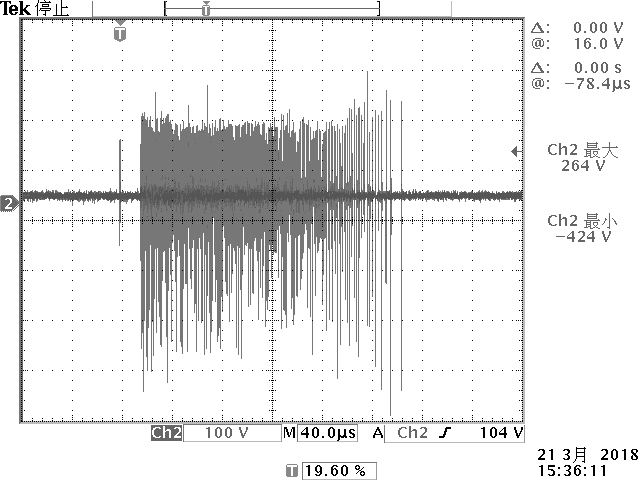
CI 220, Pulse A2-1, Mode 1
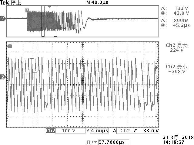
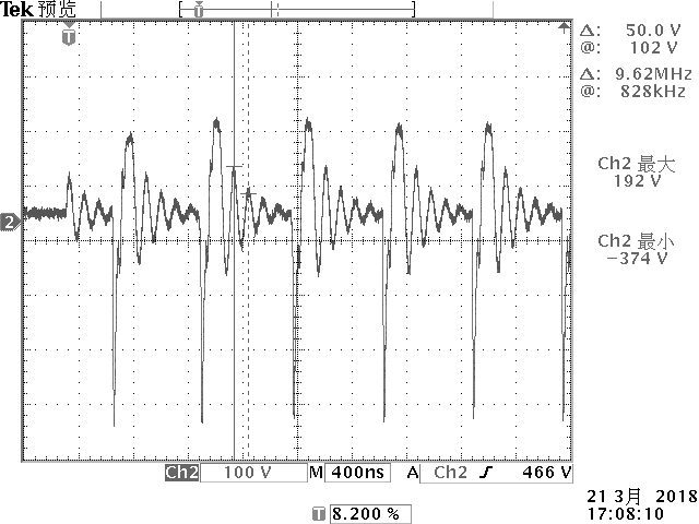
CI 220, Pulse A2-1, Mode 2
CI 220, Pulse A2-2, Mode 2
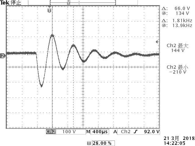
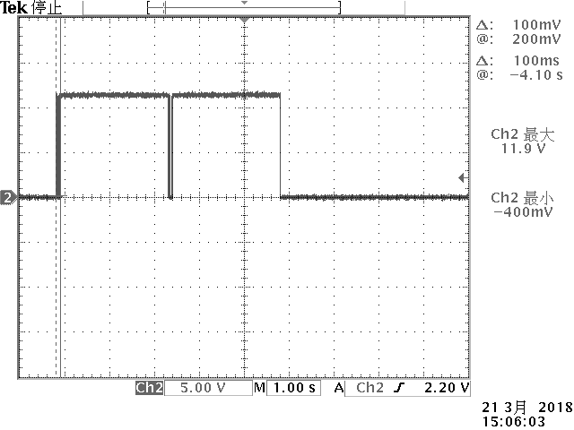
CI 220, Pulse C1, Mode 2
CI 260, Waveform F
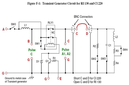
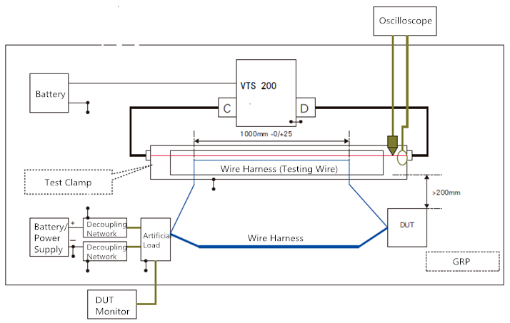
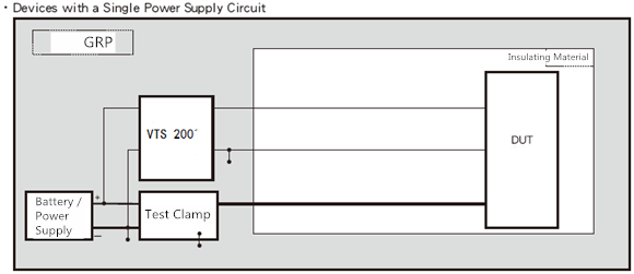
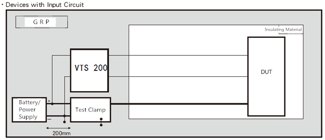
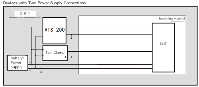
Equipment Connection Diagram
|
Technical Parameters |
|||||
|
Input Voltage |
Max 13.5 V; |
||||
|
Output Voltage |
Max 10 A – 20 A (standard 10 A relay) |
||||
|
Test Mode |
By sequence or infinite loop |
||||
|
Resistor R1 |
51 Ω, 25 W |
||||
|
Resistor R2 |
220 Ω ± 5%, 2 W |
||||
|
Resistor R3 |
33 Ω ± 5%, 10 W |
||||
|
Resistor R4 |
6 Ω ± 5%, 50 W |
||||
|
Capacitor C1 |
100 nF capacitor, 400 V |
||||
|
Inductor L1 |
5 μH inductor |
||||
|
Inductor L2 |
100 mH inductor |
||||
|
Diode D1 |
Zener diode, 39 V, 5 W |
||||
|
Transistor Q1 |
NPN transistor |
||||
|
SW0 - SW4 |
Single Throw Switch |
||||
|
RLY1 |
12 V AC relay, NC contact used (Potter & Brumfield KUP-14A15-12) |
||||
|
Test Procedures |
|||||
|
As per EMC-CS-2009 FMC1278-2016 |
CI 220: A1, Mode M1, M2 CI 220: A2-1, Mode M1, M2, M3 CI 220: A2-2, Mode M1, M2, M3 CI 220: C-1, Mode M2, M3 CI 220: C-2, Mode M2 和 M3 |
||||
|
CI 260: F |
|||||
|
RI 130: A2-1, Mode M2 and M3; RI 130: A2-2, Mode M2 and M3; Specific type of test clamp shall be used. |
|||||
|
Output Waveforms and Current |
|||||
|
Tests |
Output Waveform |
Mode |
Time *1 |
Max Output Voltage |
Output Terminal |
|
RI 130 |
A2-1 |
2 |
60 |
*2 |
SOURCE SINK |
|
3 |
|||||
|
A2-2 |
2 |
||||
|
3 |
|||||
|
CI 220 |
A1 |
1 |
120 |
10 |
PULSE A, F+ GND- |
|
2 |
|||||
|
A2-1 |
1 |
||||
|
2 |
20 |
||||
|
3 |
|||||
|
A2-2 |
1 |
||||
|
2 |
|||||
|
3 |
|||||
|
C-1 |
2 |
50 |
PULSE C, F+ GND- |
||
|
3 |
|||||
|
C-2 |
2 |
||||
|
3 |
|||||
|
CI 260 |
F |
- |
60 |
10 |
PULSE A, F+ GND- |
|
General Parameters |
|||||
|
Fuse |
20 A, for DUT power supply current |
||||
|
Protection |
Over-voltage protection and reverse polarity protection |
||||
|
Power Supply |
12 V battery or APS/APG series |
||||
|
Operating Temp. |
15 - 35 ℃ |
||||
|
Operating Humidity |
35%-85%RH (no condensation) |
||||
|
Dimension |
335 x 310 x 195 mm |
||||
|
Weight |
Approx 7.2 kg |
||||
|
Input and Output Method |
|||||
|
Input |
Via 4 mm safety connector, for DC power supply |
||||
|
Output |
Via 4 mm safety connector, for CI 220, CI 260 tests; 50 Ω BNC connector for RI 130 tests; |
||||
|
LED Indicators |
Test status, Test items (ID); Waveform; Mode; |
||||
|
Standard Accessories |
||
|
Grounding cable |
1 pc |
|
|
Power supply cable |
1 pc |
|
|
Testing wire |
1 pc |
|
|
Fuse |
1 pc |
|
|
BNC cable |
1 pc |
|
|
Factory Inspection Report |
1 pc |
|
|
Quality Guarantee |
1 pc |
|
|
User manual |
1 pc |
|
|
Optional Accessories |
||
|
Test Clamp – TF 1315 |
Dimension: 1,345 x 110 x 152 mm; |
|
|
Weight: 5 kg |
||
|
Relay – |
Switch voltage: 12 V; |
 |
|
KUP-14A15-12 |
Switch current: 10 A; |
|
|
|
Triggering mode: 3PDT; |
|