When an aircraft is flying in severe convection environment, it will be frequently affected by lightning stroke, which will generate transient induced voltage or current on circuits and cables of airborne equipment, such phenomenon is called indirect lightning effect. It may make the aircraft get out of control, even bring about fuselage fire and other serious accidents. For safety reasons, the airborne equipment must be designed properly and tested completely to ensure the system and equipment with critical safety function to perform normally and its flight security when the aircraft is influenced by lightning stroke.
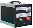
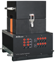
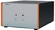
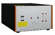
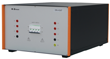
The LSS 160SM6 and LIS 100B test systems are designed according to RTCA/DO-160 Section 22, The LSS 160SM6 is capable of generating waveforms 1,4 and 5A/5B, and LIS 100B is of waveforms 2, 3 and 6. Both test level are from 1 to 3 for pins injection test and cable bundle test; Additionally, the test system is not only meet the test requirement of lightning induced transients conducted susceptibility in MIL-STD-461G CS117.
The test system includes various test auxiliary equipment to make it convenient to conduct tests, such as coupling transformer, power blocking device, transient blocking device, pin injection probe, external DC capacitor etc. What’s more, the Corelab software is also available for remote control test, which makes your test easy and convenient.
Features:
> Modular design, the waveform module is detachable;
> Capable of generating 6 kinds of waveforms and performing pins injection test and cable bundle test;
> 5.7 inch color touch screen with easy and distinct operation control;
> Phase synchronization function in signal pins & power pins-direct injection method;
> Corelab software is available for remote control.
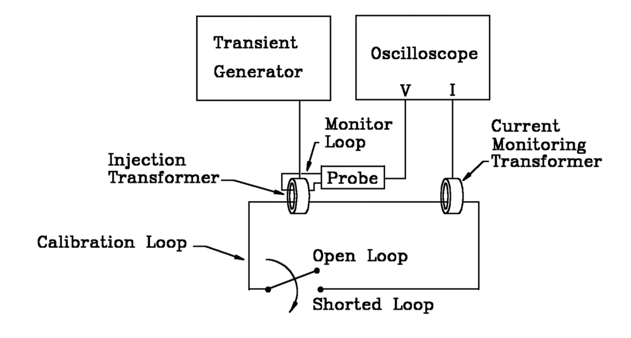
1、Calibration diagram:
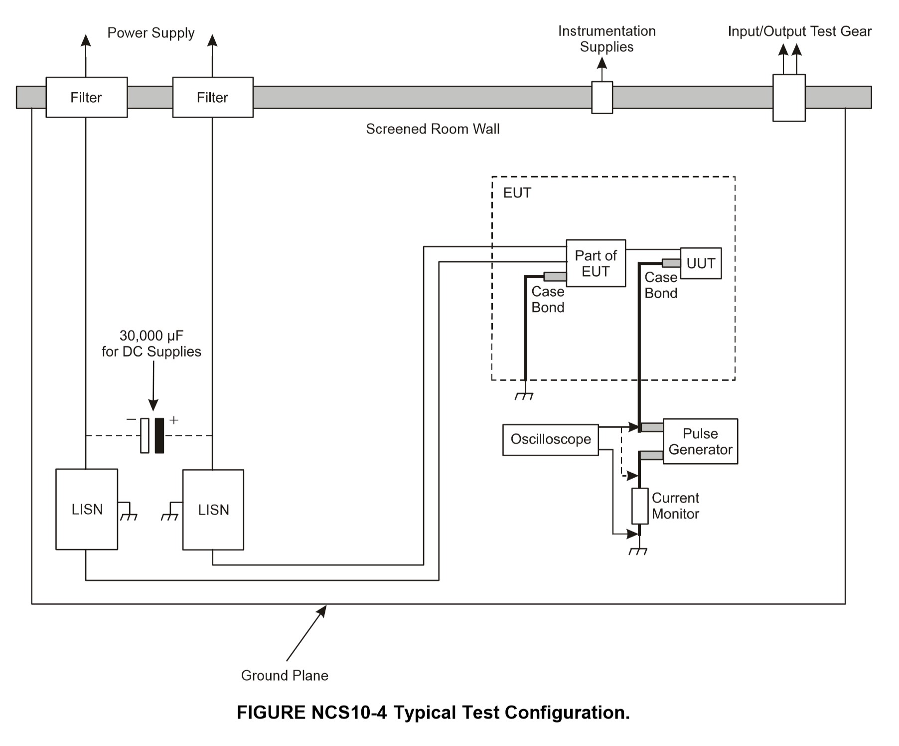
2、Test diagram:
|
Technical Parameters – LSS 160SM6 |
||
|
W1 |
||
|
Coupling Mode |
Cable Induction (CI) |
Ground Injection (GI) |
|
Module Selection |
Wave 1-CI/GI |
Wave 1-CI/GI |
|
Current Waveform |
6.4 μs ± 20% / 69 μs ± 20% |
6.4 μs ± 20% / 69 μs ± 20% |
|
Single-Stroke |
25 A – 1000 A +20%, -0% |
25 A – 1000 A +20%, -0% |
|
Multiple-Stroke |
25 A – 1000 A +20%, -0% (First stroke); 25 A – 500 A +50%, -0% (Subsequent stroke) |
25 A – 1000 A +20%, -0% (First stroke); 25 A – 500 A +50%, -0% (Subsequent stroke) |
|
No. of Subsequent Strokes |
1 – 14 adjustable |
1 – 14 adjustable |
|
Time Intervals of Subsequent Strokes |
10 ms – 200 ms adjustable, uniformity mode or random mode |
10 ms – 200 ms adjustable, uniformity mode or random mode |
|
Polarity |
+, - |
+, - |
|
Current Coupling Device |
LCVT-L3 |
LCVT-L3 |
|
No. of Tests |
1 – 99 |
1 – 99 |
|
Test Repetition |
30 s – 99 s (the min. depends on the output amplitude) |
30 s – 99 s (the min. depends on the output amplitude) |
|
EUT Load Capacity |
/ |
AC 230 V, 16 A, 50 Hz / 60 Hz, & DC |
|
Technical Parameters –LSS 160SM6 |
||
|
W4 |
||
|
Coupling Mode |
Cable Induction (CI) |
Ground Injection (GI) |
|
Module Selection |
Wave 4-CI/GI |
Wave 4-CI/GI |
|
Voltage Waveform |
6.4 μs ± 20% / 69 μs ± 20% |
6.4 μs ± 20% / 69 μs ± 20% |
|
Single-Stroke |
10 V – 1,700 V +20%, -0% |
10 V – 1,700 V +20%, -0% |
|
Multiple-Stroke |
10 V – 1,700 V +20%, -0% (First stroke); 10 V – 500 V +50%, -0% (Subsequent stroke) |
10 V – 1,700 V +20%, -0% (First stroke); 10 V – 500 V +50%, -0% (Subsequent stroke) |
|
No. of Subsequent Strokes |
1 – 14 adjustable |
1 – 14 adjustable |
|
Time Intervals of Subsequent Strokes |
10 ms – 200 ms adjustable, uniformity mode or random mode |
10 ms – 200 ms adjustable, uniformity mode or random mode |
|
Polarity |
+, - |
+, - |
|
Voltage Coupling Device |
LCVT-L3 |
LCVT-L3 |
|
No. of Tests |
1 – 99 |
1 – 99 |
|
Test Repetition |
10 s – 99 s (the min. depends on the output amplitude) |
10 s – 99 s (the min. depends on the output amplitude) |
|
EUT Load Capacity |
/ |
AC 230 V, 16 A, 50 Hz / 60 Hz, & DC |
|
Technical Parameters – LSS 160SM6 |
||
|
W4 |
||
|
Coupling Mode |
Pin Injection (PI) |
|
|
Module Selection |
Wave 4-PI |
|
|
Output Impedance |
5 Ω ±10% |
|
|
Voltage/Current Waveform |
6.4 μs ±20% / 69 μs±20% |
|
|
Single-Stroke |
25 V – 800 V +10%, -0% (open-circuit voltage); 5 A – 160 A +10%, -0% (short-circuit current); |
|
|
Polarity |
+, - |
|
|
No. of Tests |
1 - 99 |
|
|
Test Repetition |
10 s – 99 s (the min. depends on the output amplitude) |
|
|
EUT Power Sync |
Synchronized automatically with AC power peak value or 0°~359° (resolution 1°, tolerance less than 10°) |
|
|
EUT Load Capacity |
AC 230 V, 800 Hz |
|
|
Technical Parameters – LSS 160SM6 |
||
|
W5A |
||
|
Coupling Mode |
Cable Induction (CI) |
Ground Injection (GI) |
|
Module Selection |
Wave 5A-CI/GI |
Wave 5A-CI/GI |
|
Current Waveform |
40 μs ± 20% / 120 μs ± 20% |
40 μs ± 20% / 120 μs ± 20% |
|
Single-Stroke |
20 A – 2,000 A +20%, -0% |
20 A – 2,000 A +20%, -0% |
|
Multiple-Stroke |
20 A – 2,000 A +20%, -0% (First stroke); 20 A – 1000 A +50%, -0% (Subsequent stroke) |
20 A – 2,000 A +20%, -0% (First stroke); 20 A – 1000 A +50%, -0% (Subsequent stroke) |
|
No. of Subsequent Strokes |
1 – 14 adjustable |
1 – 14 adjustable |
|
Time Intervals of Subsequent Strokes |
10 ms – 200 ms adjustable, uniformity mode or random mode |
10 ms – 200 ms adjustable, uniformity mode or random mode |
|
Polarity |
+, - |
+, - |
|
Current Coupling Device |
LCVT-L3 |
LCVT-L3 |
|
No. of Tests |
1 – 99 |
1 – 99 |
|
Test Repetition |
30 s – 99 s (the min. depends on the output amplitude) |
30 s – 99 s (the min. depends on the output amplitude) |
|
EUT Load Capacity |
/ |
AC 230 V, 16 A, 50 Hz / 60 Hz, & DC |
|
Technical Parameters – LSS 160SM6 |
||
|
W5B |
||
|
Coupling Mode |
Cable Induction (CI) |
Ground Injection (GI) |
|
Module Selection |
Wave 5B-CI/GI |
Wave 5B-CI/GI |
|
Current Waveform |
50 μs ± 20% / 500 μs ± 20% |
50 μs ± 20% / 500 μs ± 20% |
|
Single-Stroke |
25 A – 2,000 A +20%, -0% |
25 A – 2,000 A +20%, -0% |
|
Multiple-Stroke |
25 A – 2,000 A +20%, -0% (First stroke); 25 A – 1000 A +50%, -0% (Subsequent stroke) |
25 A – 2,000 A +20%, -0% (First stroke); 25 A – 1000 A +50%, -0% (Subsequent stroke) |
|
No. of Subsequent Strokes |
1 – 14 adjustable |
1 – 14 adjustable |
|
Time Intervals of Subsequent Strokes |
30 ms – 200 ms adjustable, uniformity mode or random mode |
30 ms – 200 ms adjustable, uniformity mode or random mode |
|
Polarity |
+, - |
+, - |
|
Current Coupling Device |
LCVT-L3 |
LCVT-L3 |
|
No. of Tests |
1 – 99 |
1 – 99 |
|
Test Repetition |
30 s – 99 s (the min. depends on the output amplitude) |
30 s – 99 s (the min. depends on the output amplitude) |
|
EUT Load Capacity |
/ |
AC 230 V, 16 A, 50 Hz / 60 Hz, & DC |
|
Technical Parameters – LSS 160SM6 |
||
|
W5A |
||
|
Coupling Mode |
Pin Injection (PI) |
|
|
Module Selection |
Wave 5A-PI |
|
|
Output Impedance |
1 Ω ±10% |
|
|
Voltage/Current Waveform |
40 μs ± 20% / 120 μs ± 20% |
|
|
Single-Stroke |
25 V – 800 V +10%, -0% (open-circuit voltage); 25 A – 800 A +10%, -0% (short-circuit current); |
|
|
Polarity |
+, - |
|
|
No. of Tests |
1 - 99 |
|
|
Test Repetition |
30 s – 99 s (the min. depends on the output amplitude) |
|
|
EUT Power Sync |
Synchronized automatically with AC power peak value or 0°~359° (resolution 1°, tolerance less than 10°) |
|
|
EUT Load Capacity |
AC 230 V, 800 Hz |
|
|
Technical Parameters – LSS 160SM6 |
||
|
W5B |
||
|
Coupling Mode |
Pin Injection (PI) |
|
|
Module Selection |
Wave 5B-PI |
|
|
Output Impedance |
1 Ω ±10% |
|
|
Voltage/Current Waveform |
50 μs ± 20% / 500 μs ± 20% |
|
|
Single-Stroke |
25 V – 800 V +10%, -0% (open-circuit voltage); 25 A – 800 A +10%, -0% (short-circuit current); |
|
|
Polarity |
+, - |
|
|
No. of Tests |
1 - 99 |
|
|
Test Repetition |
30 s – 99 s (the min. depends on the output amplitude) |
|
|
EUT Power Sync |
Synchronized automatically with AC power peak value or 0°~359° (resolution 1°, tolerance less than 10°) |
|
|
EUT Load Capacity |
AC 230 V, 800 Hz |
|
|
Technical Parameters – LIS 100B |
||
|
W2 |
||
|
Coupling Mode |
Cable Induction (CI) |
|
|
Rise Time |
< 100 ns |
|
|
Duration |
6.4 μs ±20% |
|
|
Single-Stroke |
25 V – 1,600 V +20%, -0% |
|
|
Multiple-Stroke |
25 V – 750 V +20%, -0% (First stroke); 12.5 V – 350 V +50%, -0% (Subsequent Stroke) |
|
|
Test Repetition |
1.5 s – 60 s (the min. depends on the output amplitude) |
|
|
Polarity |
+, - |
|
|
High-Frequency Voltage Coupling Transformer |
LVT-2 |
|
|
Technical Parameters – LIS 100B |
||
|
W3 |
||
|
Coupling Mode |
Pin Injection (PI) |
|
|
Module Selection |
W3 – 1 MHz |
|
|
Output Impedance |
25 Ω |
|
|
Voltage/Current Repetition |
1 MHz ±20% |
|
|
Attenuation of 5th Stroke |
25% - 75% |
|
|
Single-Stroke |
50 V – 2000 V +10%, -0%; 2 A – 80 A +10%, -0% (short-circuit current) |
|
|
Test Repetition |
1.5 s – 60 s (the min. depends on the output amplitude) |
|
|
Polarity |
+, - |
|
|
Phase Sync. |
0° - 359°, 1° step |
|
|
EUT Load Capacity |
AC 230 V, DC ±50 V, 800 Hz |
|
|
Technical Parameters – LIS 100B |
||
|
Coupling Mode |
Cable Induction (CI) |
Cable Induction (CI) |
|
Module Selection |
W3 – 1 MHz |
W3 – 10 MHz |
|
Voltage/Current Repetition |
1 MHz ±20% |
10 MHz ±20% |
|
Attenuation of 5th Stroke |
25% - 75% |
25% - 75% |
|
Single-Stroke |
50 V – 2000 V +20%, -0% |
50 V – 1600 V +20%, -0% |
|
Multiple-Stroke |
50 V – 2000 V +20%, -0% (First stroke); 25 V – 1000 V +50%, -0% (Subsequent stroke) |
50 V – 1600 V +20%, -0% (First stroke); 25 V – 800 V +50%, -0% (Subsequent stroke) |
|
Multiple-Burst |
50 V – 900 V +20%, -0% |
50 V – 900 V +20%, -0% |
|
Test Repetition |
1.5 s – 60 s (the min. depends on the output amplitude) |
1.5 s – 60 s (the min. depends on the output amplitude) |
|
Polarity |
+, - |
+, - |
|
High-Frequency Voltage Coupling Transformer |
LVT-2 |
LVT-2 |
|
Technical Parameters – LIS 100B |
||
|
W6 |
||
|
Coupling Mode |
Cable Induction (CI) |
|
|
Current Waveform |
5 A-75 A |
|
|
Rise Time |
0.25 μs ±20% |
|
|
Pulse Width |
4 μs ±20% |
|
|
Test Repetition |
3 s-10 s(the min. depends on the output amplitude) |
|
|
High-Frequency Voltage Coupling Transformer |
LVT-3 |
|
|
General Parameters |
||
|
Power Supply Voltage |
AC 110 V / 220 V ±10%, 50 Hz /60 Hz ±5% (Default AC 220 V 50 Hz in mainland China) |
|
|
Max Power |
200 W |
|
|
Operating Temp. |
15 ℃ - 35 ℃ |
|
|
Operating Humidity |
45% - 75% |
|
|
Operating Air Pressure |
86 kPa – 106 kPa |
|
|
Standard Accessories |
|
|
Testing Wire, Fuse *2 (spare part), User Manual, Power Wire, Coaxial Cable, Plug Clip |
|
|
Options (LSS 160SM6) |
|
|
1. Line Impedance Stabilization Network LISN AR 50
|
The LISN AR 50 is used for isolating electric wave in cable bundle test and supply stable impedance for test system; Max AC 530 V, DC 600 V I rms: 50 A; Frequency Range: 10 kHz ~ 400 MHz |
|
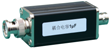
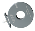
2. Coupling Transformer LCVT-L3
|
Used for coupling current waveforms of W1, W5A, and W5B; Used for W4 voltage waveform coupling; Can meet the single and multiple rebound tests of cable bundles W1, W5A, W5B current waveforms and W4 voltage waveforms |
|
3. External DC Capacitor C33600/C33500/C33400
|
The C33600/C33500/C33400 is used together with LISN for conducting cable bundle tests; Maximum DC voltage is 600 V (general configuration is 50 V); Capacitance: 33000 μF |
|
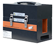
4. Power Blocking Device CN-1
|
Used to isolate the voltage on the EUT pin from the low source impedance of the signal generator, protecting the signal generator; |
|
5. Transient Blocking Device DN-416T
|
Used to prevent W3, W4, W5A, W5B transient waveforms from damaging
the EUT power supply; AC/power supply maximum voltage 3-phase 400 V
16 A, 0-400 Hz (common mode); DC power supply with a maximum voltage of 600 V 16 A; |
|
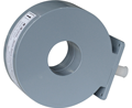
6.Coupling Transformer LVT-2
|
The LVT-2 is used to couple voltage of waveform 2 and waveform 3 (1 MHz & 10 MHz); It satisfies single stroke, multiple stroke and multiple burst tests of cable bundle; Test level is from 1 to 3; Max. coupling voltage is 2000 V for W2; Max. coupling voltage is 4000 V for W3 |
|
7.Coupling Transformer LVT-3
|
The LVT-3 is used to couple current of waveform 6; It satisfies multiple burst tests of cable bundle; Test level is from 1 to 3; Max. coupling current is 160 A |
|
8.Power Blocking Device CN-2
|
The CN-2 is used to isolate voltages at the pins of the EUT from the low generator impedance in waveform 3 pins direct injection test |
|
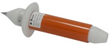
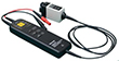
9.Handheld Pin Injection Probe HIP 5000
|
The probe is used in pin injection tests of waveform 3 (1 MHz); Handheld structure design makes pin injection tests convenient |
|
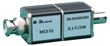
10.Current Divider MCS 01
|
The MCS 01 is used to measure current of waveforms 2, 3 and 6 |
|
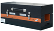
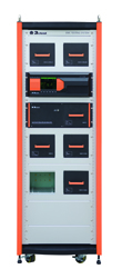
11.35U rack ETS 160MB-35U
|
The 35U rack is used to place all devices and accessories to makes the storage in order; There are two main unit storage tanks and four waveform input modules storage tanks, and each tank having sliding rail, which makes it easy to insert or pull out the modules |
|
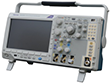
12.Digital Oscilloscope MDO3012 (Tektronix)
|
Frequency 100 MHz; Sample Rate 1.25 GS/s; Record length 10 Mb
|
|
13.Wide-band Current Monitor CM 0220M
|
Max. peak current 20 kA; Sensitivity 0.01 V/A; Current time product: 1 A·s
|
|
14.Wide-band Current Monitor CM 0302M
|
Max. peak current 200 kA; Sensitivity 0.001 V/A; Current time product: 10 A·s
|
|
15.Differential Probe THDP0100 (Tektronix)
|
6 kV differential mode, 100 MHz; The THDP0100 is used for measuring voltage of all waveforms
|
|
Control Software |
|
|
Corelab
|
The software is used for remote control; Support connection with oscilloscope for monitoring waveforms; Support generating test report. |