External automatic coupling / decoupling network;
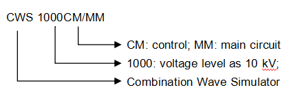
Naming Rules:

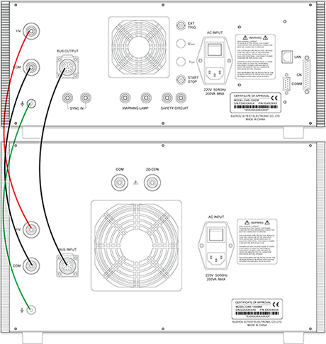
Equipment Connection Diagram:


|
Technical Parameters - 1.2/50 μs, 8/20 μs |
|
|
|
Test Voltage |
0.5 kV –10.0 kV ± 10% |
|
|
Voltage Tr |
1.2 μs ± 30% |
|
|
Voltage Td |
50 μs ± 20% |
|
|
Test Current |
0.25 kA–5.0kA± 10% (2ohm) |
|
|
Current Tr |
8 μs ± 20% |
|
|
Current Td |
20 μs ± 20% |
|
|
Output Impedance |
2 ohm or 12 ohm |
|
|
Test Interval |
6 s – 99 s (the shortest time subject to test voltage) |
|
|
Measuring Of Peak Voltage |
Via BNC on Front Panel: 1000V:1V; Results shown on LCD; |
|
|
Measuring Of Peak Current |
Via BNC on Front Panel: 100A:1V; Results shown on LCD; |
|
|
No. Of Tests |
1 – 999 |
|
|
Triggering Mode |
Automatic, manual, or external triggering |
|
|
Test Method |
As per standard test requirements |
|
|
Technical Parameters - 1.2/50 μs |
|
|
|
Test Voltage |
0.5 kV–10.0 kV± 10% |
|
|
Voltage Tr |
1.2 μs ± 30% |
|
|
Voltage Td |
50 μs ± 20% |
|
|
Output Impedance |
500 ohm |
|
|
Test Interval |
5 s – 99 s (the shortest time subject to test voltage) |
|
|
Measuring Of Peak Voltage |
Via BNC on Front Panel: 1000V:1V; Results shown on LCD; |
|
|
No. Of Tests |
1–999 |
|
|
Triggering Mode |
Automatic, manual, or external triggering |
|
|
Test Method |
As per standard test requirements |
|
|
Technical Parameters - 10/700 μs, 5/320 μs |
|
|
|
Test Voltage |
0.5 kV –10.0 kV ± 10% |
|
|
Voltage Tr |
10 μs ± 20% |
|
|
Voltage Td |
700 μs ± 20% |
|
|
Current Tr |
5 μs ± 20% |
|
|
Current Td |
320 μs ± 20% |
|
|
Output Impedance |
15ohm or 40ohm optional |
|
|
Test Interval |
11 s - 99 s (the shortest time subject to test voltage) |
|
|
Measuring Of Peak Voltage |
Via BNC on Front Panel: 1000V:1V; Results shown on LCD; |
|
|
Measuring Of Peak Current |
Via BNC on Front Panel: 100A:1V; Results shown on LCD; |
|
|
No. Of Tests |
1–999 |
|
|
Triggering Mode |
Automatic, manual, or external triggering |
|
|
Test Method |
As per standard test requirements |
|
|
General Parameters |
||
|
Display |
5.7” TFT color touch screen |
|
|
Operating Voltage |
AC 110V/220V ±10, 50/60Hz |
|
|
Fuse |
6 A |
|
|
Capacity |
200 W |
|
|
Storage Space |
Unlimited (PC) |
|
|
Communication Method |
Ethernet, RJ45 |
|
|
Safety Circuit |
Not operating if the open safety circuit is not closed |
|
|
Error Detection |
Errors will be shown on LCD while operation will be stopped. |
|
|
Output Measuring Method |
Via 1 m co-axial stable |
|
|
Dimension (W x H x D) |
19”, 4U (CWS 1000CM) + 6U (CWS 1000MM) |
|
|
Weight |
About 40 Kg |
|
|
Operating Temp. |
15℃ – 35℃ |
|
|
Operating Humidity |
45% - 75% |
|
|
Operating Air Pressure |
86 kPa - 106 kPa |
|
|
Standard Accessories |
|
|
Testing wire |
1 pc |
|
Power supply cable |
1 pc |
|
Fuse |
1 pc |
|
Factory Inspection Report |
1 pc |
|
User Manual |
1 pc |
|
Optional Accessories |
|
|
1. CDN for Surge immunity tests as per IEC 61000-4-5: SPN series: SPN 2216S10 (10 kV external single-phase); SPN 3816S10 (10 kV external single-phase); SPN 3816T10 (10 kV external 3-phase) SPN 3832T10 (10 kV external 3-phase) |
|
|
2. CDN for signal lines as per IEC 61000-4-5: CDN 405 series (10 kV or to be customized) |
|
|
3. HV differential probe VCF-80: Test voltage 8 kV, attenuation: 1000:1 |
|
|
4. Wide-band Current Monitor CM 0220M |
|