


This lightning direct effect testing system includes a high-voltage attachment point zoning test system and a high current physical damage test system. The high-voltage attachment point zoning test system can simulate and test the probability of aircraft and other equipment being struck by lightning in different areas of the aircraft surface, and find attachment points that are prone to lightning strikes. The high current physical damage test system is used to simulate the damage effects of high temperature and strong electric force on the aircraft structure and other parts caused by the high current at the attachment point of the aircraft when it is struck by lightning.
High current injection test system
summary
When flying in severe convective
weather, airplanes are susceptible to direct adhesion from lightning,
generating high temperatures, high voltages, and strong electromagnetic
forces, which can cause combustion, corrosion, explosion, structural
distortion, and strength reduction effects on the aircraft. The aircraft
lightning protection testing system independently developed by our company is
a very complex pulse current testing system, which fully complies with the
requirements of aircraft lightning protection standards such as MIL-STD-464C,
SAE ARP5412, DO160 section 23, etc. The simulated direct attached lightning
strike area of the aircraft should withstand a continuous waveform composed
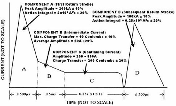
of four waveforms, ABCD, for direct effect lightning strikes. The entire
system includes four sets of pulse current generators.
Introduction to waveform
The LCG 464C aircraft lightning direct
effect high current injection test system mainly includes six waveforms: A
(AH), B, C (C *), and D, as shown in the following figure.
Waveform A
The peak current is 200 kA ± 10%, with an integral
of 2 × 10⁶A2S ± 20% (within
500 μ s). The rise time (10% -90% before the peak) is
not more than 50 μ s, and the time for the current to
decay to 1% of the peak is not more than 500 μ s. At
this stage, the current can be unidirectional or oscillatory.
Waveform AH
The peak current is 150 kA ± 10%, with an integral
of 0.8 × 10⁶A2S ± 20% (within
500 μ s). The rise time (10% -90% before the peak) is
not more than 37.5 μ s, and the time for the current
to decay to 1% of the peak is not more than 500 μ s.
At this stage, the current can be unidirectional or oscillatory.
Waveform B
The average current amplitude is 2 kA ± 10%, the maximum
charge is less than 10 Coulomb ± 10%, and the
duration does not exceed 5 ms. At this stage, the current must be a
unidirectional square wave current, or replaced by exponential or linear
decay current.
Waveform C
The current amplitude is 200-800 A, the
charge is 200 coulombs ± 20%, and the duration is 0.25-1s. At this stage, the current must be a
unidirectional square wave current, or replaced by exponential or linear
decay current.
Waveform C*
The average amplitude of the current is
not less than 400 A, and the duration is the residence time of the combined
waveform minus 5 ms. The duration interval of the combined waveform is 1-50
ms. At this stage, the current must be a unidirectional square wave current,
or replaced by exponential or linear decay current.
Waveform D
The peak current is 100 kA ± 10%, with
unidirectional or oscillating current. The rise time (10% -90% before the
peak) is not more than 25 μ s, and the time for the
current to decay to 1% of the peak is not more than 500 μ s. The integral of the action is 0.25 × 10⁶A2S ± 20% (within 500 μ s).
Configuration:
MIL-464C/DO-160G Section 23 Lightning
Direct Effect Test System Configuration:
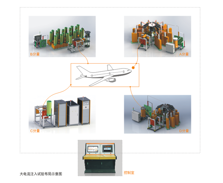
This lightning strike system mainly
includes 5 control systems, 1 measurement and analysis system, and 4
generators for generating components A, B, C, and D. Each generator
communicates with each other through an industrial fieldbus, allowing for
independent testing and centralized control of the 4 generators.
Generators A and D use non gap adaptive Crowbar units. Compared to gap
Crowbar, which requires impulse voltage generator triggering and secondary
delay control ignition, non gap Crowbar switches do not require impulse
voltage generator triggering or secondary delay control ignition, truly
achieving adaptive self triggering. Compared to the discharge sound of
Crowbar switches with multiple gaps, the use of non gap switches greatly
reduces the discharge noise. Its application in reducing energy storage
capacitance while improving equipment output stability.
|
Configure related attachmentsr |
|||
|
Serial number |
Name/Model |
Specifications/Parameters |
collocation method |
|
1 |
LCG 200S |
Outputwaveform: A component/wavefront less than 30 us; |
standard configuration |
|
Integral function: 2 * 106A2s |
|||
|
Peak output: 200 kA (10%~100%) |
|||
|
Can output oscillating waves when used alone |
|||
|
Equipped with touch screen control, it can run independently |
|||
|
2 |
CB100 Crowbar Unit |
Rated working voltage: 100 kV |
optional |
|
Rated current: 200 kA |
|||
|
Working mode: adaptive triggering |
|||
|
Cooperate with the A-component generator to output exponential waves |
|||
|
3 |
LCG 2M |
Output waveform: B component/square wave |
standard configuration |
|
Duration: 5 ms |
|||
|
Peak output: 2 kA (± 10%) |
|||
|
Equipped with touch screen control, it can run independently |
|||
|
4 |
CN 100 Coupling Decoupling Unit |
Coupling current: B component |
standard configuration |
|
Decoupling voltage: 100 kV |
|||
|
Decoupling pulse width: 100 us |
|||
|
Damage to the B component generator caused by parallel output of ABCD |
|||
|
5 |
LDC 200 C component generator |
Output waveform: C component/DC waveform |
standard configuration |
|
Duration: 0.02-2 seconds adjustable |
|||
|
Output amplitude: 200 A (2 s), 400 A (0.5 s) |
|||
|
Equipped with touch screen control, it can run independently |
|||
|
6 |
CN 100 Coupling Decoupling Unit |
Coupling current: C component |
standard configuration |
|
Decoupling voltage: 100 kV |
|||
|
Decoupling pulse width: 100 us |
|||
|
Damage to the C-component generator caused by parallel output of ABCD |
|||
|
7 |
DN5200 secondary decoupling Unit |
Coupling current: 200A continuous, 800A (0.5 s) |
standard configuration |
|
Decoupling voltage: 10 kV |
|||
|
Decoupling method: differential mode decoupling |
|||
|
Used to prevent damage to the C-component generator when outputting in parallel with ABCD |
|||
|
8 |
LCG 100S |
Output waveform: D component/wavefront less than 15 us; |
standard configuration |
|
Function integral: 0.25 * 106A2s |
|||
|
Peak output: 100 kA (10%~100%) |
|||
|
Can output oscillating waves when used alone |
|||
|
Equipped with touch screen control, it can run independently |
|||
|
9 |
CB100 Crowbar Unit |
Rated working voltage: 100 kV |
optional |
|
Rated current: 200 kA |
|||
|
Working mode: adaptive triggering |
|||
|
Cooperate with the D-component generator to output exponential waves |
|||
|
10 |
MCS64C |
6-way trigger fiber optic output |
standard configuration |
|
Interval time: 0us-99s |
|||
|
Trigger time: 0us-99s |
|||
|
Using 4 Tektronix oscilloscopes for fiber networking measurement |
|||
|
Four generators can be controlled simultaneously to achieve simultaneous operation and sequential discharge. |
|||
|
MCS upper computer control measurement analysis integrated system |
|||
|
4 Wave Intelligent Analysis Combination |
|||
|
Logarithmic coordinate display |
|||


