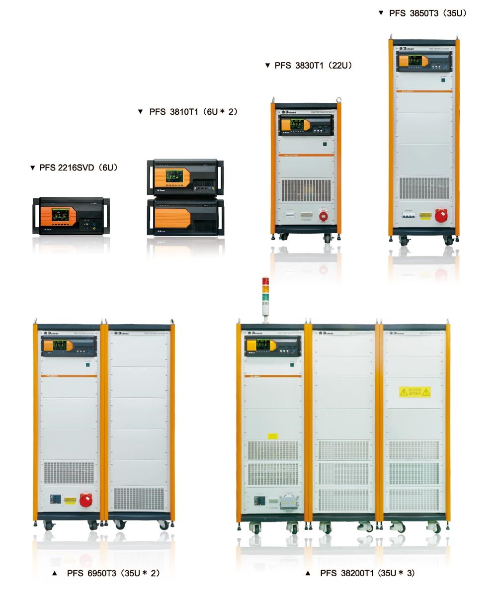


PFS series single/ three-phase power fail simulator simulates voltage dip, interruption and variation which are caused by power grid and transformer devices due to malfunction or sudden large change of load. It is required to test this kind of phenomena to check whether electronic and electrical device can sustain safety operating condition. PFS series single/ three-phase power fail simulator is equipped with controllable semi-conductor switches with protection function as per IEC 61000-4-11/34,GB/T17626.11/34.
Features:
> 5.7 inch color touch screen
> Full compliant test as per IEC 61000-4-11
> Built-in multifunctional test module
> Data acquisition of voltage and current
> Programmable test procedures
> Ethernet RJ45, PC remote control, test report documentation and print
Naming rule:


|
General parameters |
||
|
Display Screen |
5.7-inch TFT touch screen |
|
|
Power Supply for Battery Charger |
AC 110 V / 220 V,(±10%),50/60 Hz |
|
|
Fuses |
6 A |
|
|
Maximum Power Consumption |
300 W |
|
|
User Storage Space |
Infinite (PC) |
|
|
Communication Methods |
Ethernet LAN、RJ45 |
|
|
External Trigger Input |
BNC, 5 V TTL |
|
|
CRO Trigger Output |
BNC, 5 V TTL |
|
|
Operation Control input |
BNC, 5 V TTL |
|
|
External Synchronous Input |
45-65 Hz, 20-500 V between homonymous and heteronymous ends |
|
|
Failure Detection |
When it fails, the front panel LCD displays and interrupts the instrument's operation |
|
|
Instrument Working Status Indication |
Front panel LED indication, LCD display |
|
|
Instrument Grounding Connection Method |
Using a flat grounding wire |
|
|
EUT Power Supply Voltage Injection |
5-core industrial socket |
|
|
Detection Output Method |
Standard 1-meter coaxial line |
|
|
Dimension |
19-inch 6U chassis or 19 inch/22U/35U cabinet |
|
|
Weight |
6U: approx 35kg 22U: approx 150kg 35U: approx 380~467kg |
|
|
Ambient Temperature |
15 ℃ - 35 ℃ |
|
|
Relative Humidity |
45% - 75% |
|
|
Atmospheric Pressure |
86 kPa - 106 kPa |
|
|
Generator load capacity description |
||
|
Generator peak impact capability description |
||
|
Rated generator current |
The ability of the generator to withstand current shock |
|
|
50 A and below current |
500 A |
|
|
50.1 A to 100A current |
1000 A |
|
|
More than 100 A current |
Greater than 1000 A |
|
|
Generators with rated current of 16 A and below comply with IEC 61000-4-11 load capacity specification |
||
|
Rated generator current |
Generator load current capability |
|
|
PFS 3810T1 PFS 3810T1V |
12 A AC/DC continuous current; 15 A lasts 5 s; 25 A lasts for 3 s; |
|
|
PFS 3816T1 PFS 3816T1V |
18 A AC/DC continuous current; 23 A lasts 5 s; 40 A lasts for 3 s; |
|
|
Power failure testing in accordance with IEC 61000-4-11&IEC 61000-4-34 standards |
||
|
IEC/EN 61000-4-11, GB/T17626.11&IEC 61000-4-34, GB/T16626.34 Technical parameters for single/three-phase AC power supply fault simulators with voltage dips, short-term interruptions, and voltage changes |
||
|
Maximum Continuous Current of EUT |
12 A (PFSxx10xxx series) 18 A (PFSxx16xxx series) 32 A (PFSxx30xxx series) 52 A (PFSxx50xxx series) 77 A (PFSxx75xxx series) 102 A (PFSxx100xxx series) 202 A (PFSxx200xxx series) |
|
|
Resistance to Impulse Current |
50 A and below products:500 A , Products above 50 A:1000 A |
|
|
Protect |
Built in overcurrent, short circuit, overvoltage, overheating, surge, group pulse, and electrostatic protection Line in and Line out ports can be selected with other external protection accessories |
|
|
Maximum Input Voltage of EUT |
Single-phase 250 V AC±5%,50/60 Hz±5% (300 V DC optional) Three-phase: PFS38xxxx series:420 V AC,50/60 Hz±5%(300 V DC optional) PFS45xxxx series:480 V AC,50/60 Hz±5%(300 V DC optional) PFS69xxxx series:720 V AC,50/60 Hz±5%(300 V DC optional) |
|
|
EUT Current and Voltage Measurement |
LCD display |
|
|
Interrupt Level |
0% |
|
|
Voltage Interruption Mode |
Optional voltage interruption for one phase, two phases, or three phases |
|
|
Temporary Voltage Drop |
0%-100% |
|
|
Voltage Sag Method |
Temporary voltage drops between phase line and neutral line Temporary voltage drops between phase lines PFSxxxxT1:GB/T17626.34 Figure3a、b/IEC61000-4-34: Figure3a、3b PFSxxxxT3:GB/T17626.34 Figure3a、c/IEC61000-4-34: Figure3a、3c |
|
|
Duration of Temporary Suspension and Interruption |
0.3-9999 cycles or 5 ms -99999 ms (1 ms for models with suffix D) |
|
|
Temporary Lowering and Interruption Interval Time |
10 ms - 50000 ms |
|
|
Temporary Reduction and Interruption of Test Frequency |
1 - 9999 |
|
|
Temporary Descent, Interruption of Ascent, Descent Time |
Generator rated current of 75 A and below products: 1-5 μ s (standard resistance verification) Generator rated current above 75 A products: 1-50 μ s (standard resistance verification) |
|
|
Voltage Variation Level (16A and below optional) |
0-100% |
|
|
Voltage Change Reduction time (16A and below optional) |
500 ms to 9999 ms (50% -100%) or mutation (same as temporary descent, interruption of ascent, descent time) 1000 ms to 9999 ms (0% -100%) or mutation (same as temporary descent, interruption rise, descent time) |
|
|
Voltage Change increase time (16A and below optional) |
500 ms – 9999 ms(50%-100%) 1000 ms – 9999 ms(0%-100%) |
|
|
Duration of Voltage Change After Decrease (16A and below optional) |
10 ms - 99999 ms |
|
|
Synchronization |
0 ° -360 °, 1 ° step setting or random mode |
|
|
Trigger Method |
Manual, automatic, external trigger input |
|
|
Optional Accessories |
|
Testing system PFS, expandable accessories, power cables, EUT power cables, network cables, factory inspection reports, manuals |