


Introduction:
When an aircraft is flying in severe convection environment, it will be frequently affected by lightning stroke, which will generate transient induced voltage or current on circuits and cables of airborne equipment, such phenomenon is called indirect lightning effect. It may make the aircraft get out of control, even bring about fuselage fire and other serious accidents. For safety reasons, the airborne equipment must be designed properly and tested completely to ensure the system and equipment with critical safety function to perform normally and its flight security when the aircraft is influenced by lightning stroke.
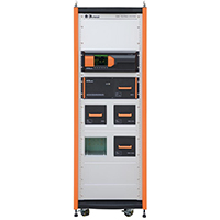
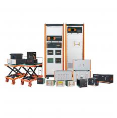
The LSS 160SM8 and ETS 160MB test systems are designed according to RTCA/DO-160 Section 22, The LSS 160SM8 is capable of generating waveforms 1,4 and 5A/5B, and ETS 160MB is of waveforms 2, 3 and 6. Both test level are from 1 to 5 for pins injection test and cable bundle test; Additionally, the test system is not only meet the test requirement of lightning induced transients conducted susceptibility in MIL-STD-461G CS117, but also the A/B/C/D EUT pulse injection level requirement in GJB 8848: 2016 is satisfied.
Features:
> Modular design and structure of the whole machine, with independent and pluggable waveform output modules, meeting various relevant test standards and different waveform requirements;
> Capable of outputting 6 types and 8 types of waveforms; Can perform pin injection test and cable bundle test;
> 5.7” color touch screen with easy and distinct operation control;
> Phase synchronization function in signal pins & power pins-direct injection method;
> Corelab software are available for remote control;
|
Technical Parameter for LSS 160SM8 |
|
|
Technical Parameters—Current Waveform 1 Cable Bundle and Ground Induction |
|
|
For Tests As Per DO-160G S22, MIL-STD-461G CS117(WF2/1) |
|
|
Coupling Mode |
Cable induction (CI) Ground injection (GI) |
|
Output Module |
W1 CI/GI |
|
Current Waveform 1 |
6.4 μs ± 20% / 69 μs ± 20% |
|
Single Stroke Output |
W1 CI/GI:50 A ~ 4200 A (-0%~+20%); Output impedance≤0.5 Ω |
|
Multiple Stroke Output |
50 A ~2000 A (-0%~+20%) (first stroke); |
|
25 A ~ 1000 A (-0%~+50%) (subsequent
stroke); |
|
|
Number of Subsequent Pulses |
1 ~ 14 |
|
Interval Time of Subsequent Pulses |
10 ms ~ 200 ms, Random mode is available |
|
Polarity |
Positive or negative |
|
Number of Test Times |
1 ~ 99 |
|
Test Repetition |
10 s ~ 99 s (shortest time depends on output amplitude) |
|
Coupler |
LCT- L5B |
|
Maximum EUT Power Supply |
Cable Induction (CI):none |
|
Output Module |
WAVE 1 CI/GI IH |
|
Single Stroke Output |
50 A ~ 3200 A (-0%~+20%); |
|
Multiple Stroke Output |
50 A ~ 1600 A (-0%~+20%) (first stroke) |
|
25 A ~ 800 A (-0%~+50%) (subsequent stroke); |
|
|
Technical Parameters—Voltage Waveform 4 Signal Pins & Power Pins Direct Injection |
|
|
For Tests As Per DO-160G S22 |
|
|
Coupling Mode |
Pins direct injection (PDI) |
|
Output Module |
W4 PI |
|
Output Impedance |
5 Ω ± 10 % |
|
Voltage/Current Waveform 4 |
6.4 μs ± 20% / 69 μs ± 20% |
|
Output Voltage |
50 V ~ 3000 V (-0%~+10%), (open circuit) |
|
Output Current |
10 A ~ 600 A (-0%~+10%),(short circuit) |
|
Polarity |
Positive or negative |
|
Number of Test Times |
1 ~ 99 |
|
Test Repetition |
10 s ~ 99 s (shortest time depends on output amplitude) |
|
EUT Power Supply |
Max. 230 V |
|
EUT Frequency |
Max. 800 Hz |
|
Power Blocking Device |
Greater than peak value of signal or power voltage (optional) |
|
Technical Parameters—Voltage Waveform 4 Cable Bundle and Ground Injection |
|
|
For Tests As Per DO-160G S22 |
|
|
Coupling Mode |
Cable induction (CI) |
|
Ground injection (GI) |
|
|
Output Module |
W4 CI/GI |
|
Voltage Waveform 4 |
6.4 μs ± 20% / 69 μs ± 20% |
|
Single Stroke Output |
50 V ~ 3000 V (-0%~+20%); |
|
Output impedance≥0.5 Ω |
|
|
Multiple Stroke Output |
25 V ~ 1000 V (-0%~+20%) (first stroke); |
|
10 V ~ 500 V (-0%~+50%) (subsequent stroke); |
|
|
Number of Subsequent pulses |
1 ~ 14 |
|
Interval Time of Subsequent Pulses |
10 ms ~ 200 ms, Random mode is also available |
|
Polarity |
Positive or negative |
|
Number of Test Times |
1 ~ 99 |
|
Test Repetition |
10 s ~ 99 s (shortest time depends on output amplitude) |
|
Coupler |
LVT-L5B |
|
Maximum EUT Power Supply |
Cable induction (CI):none |
|
Ground injection (GI):AC 230 V / 32 A 50/60 Hz; DC 230 V/32 A |
|
|
Technical Parameters—Voltage Waveform 5A Signal Pins & Power Pins Direct Injection |
|
|
For Tests As Per DO-160G S22 |
|
|
Coupling Mode |
Pins direct injection(PDI) |
|
Output Module |
W5A PI |
|
Output Impedance |
1 Ω ± 10 % |
|
Voltage/Current Waveform 5A |
40 μs ± 20 % / 120 μs ± 20 % |
|
Output Voltage |
50 V ~ 3000 V (-0%~+10%) (open circuit) |
|
Output Current |
50 A ~ 3000 A (-0%~+10%) (short circuit) |
|
Polarity |
Positive or negative |
|
Number of Test Times |
1 ~ 99 |
|
Test Repetition |
10 s ~ 99 s (shortest time depends on output amplitude) |
|
EUT Power Supply |
Max. 230 V |
|
EUT Power Frequency |
Max. 800 Hz |
|
Power Blocking Device |
Greater than peak value of signal or power voltage (optional) |
|
Technical Parameters—Current Waveform 5A Cable Bundle and Ground Induction |
|
|
For Tests As Per DO-160G S22, MIL-STD-461G CS117(WF4/5A) |
|
|
Coupling Mode |
Cable induction (CI) |
|
Ground injection (GI) |
|
|
Output Module |
W5A CI/GI |
|
Current Waveform 5A |
40 μs ± 20% / 120 μs ± 20% |
|
Single Stroke Output |
50 A ~ 10000 A (-0%~+20%); |
|
Multiple Stroke Output |
50 A ~ 2000 A (-0%~+20%) (first stroke); |
|
25 A ~ 1000 A (-0%~+50%) (subsequent stroke); |
|
|
Number of Subsequent pulses |
1 ~ 14 |
|
Interval Time of Subsequent Pulses |
10 ms ~ 200 ms, Random mode is also available |
|
Polarity |
Positive or negative |
|
Number of Test Times |
1 ~ 99 |
|
Test Repetition |
10 s ~ 99 s (shortest time depends on output amplitude) |
|
Coupler |
LCT- L5B |
|
Maximum EUT Power Supply |
Cable induction (CI):none |
|
Ground injection (GI):AC 230 V / 32 A 50/60 Hz; DC 230 V/32 A |
|
|
Technical Parameters—Voltage Waveform 5B Signal Pins & Power Pins Direct Injection |
|
|
For Tests As Per DO-160G S22 |
|
|
Coupling Mode |
Pins direct injection(PDI) |
|
Output Module |
W5B PI |
|
Output Impedance |
1 Ω ± 10% |
|
Voltage/Current Waveform 5B |
50 μs ± 20% / 500 μs ± 20% |
|
Single Stroke Output |
50 V ~ 1600 V (-0%~+10%) (open circuit) |
|
50 A ~ 1600 A (-0%~+10%) (short circuit) |
|
|
Polarity |
Positive or negative |
|
Number of Test Times |
1 ~ 99 |
|
Test Repetition |
10 s ~ 99 s (shortest time depends on output amplitude) |
|
EUT Power Supply |
Max. AC/DC 230 V |
|
EUT Power Frequency |
Max. 800 Hz |
|
Power Blocking Device |
Greater than peak value of signal or power voltage (optional) |
|
Technical Parameters—Current Waveform 5B Cable Bundle and Ground Induction |
|
|
For Tests As Per DO-160G S22 |
|
|
Coupling Mode |
Cable injection (CI) |
|
Ground injection (GI) |
|
|
Output Module |
W5B CI/GI |
|
Current Waveform 5B |
50 μs ± 20% / 500 μs ± 20% |
|
Single Stroke Output |
50 A ~ 5000 A (-0%~+20%) |
|
Multiple Stroke Output |
50 A ~ 2000 A (-0%~+20%) (first stroke); |
|
25 A ~ 1000 A (-0%~+50%) (subsequent stroke); |
|
|
Number of Subsequent pulses |
1 ~ 14 |
|
Interval Time of Subsequent Pulses |
30 ms ~ 200 ms, Random mode is also available |
|
Polarity |
Positive or negative |
|
Number of Test Times |
1 ~ 99 |
|
Test Repetition |
10 s ~ 99 s (shortest time depends on output amplitude) |
|
Coupler |
LCT - L5B |
|
Maximum EUT Power Supply |
Cable induction (CI):none |
|
Ground injection (GI):AC 230 V / 32 A 50/60 Hz; DC 230 V/32 A |
|
|
Technical Parameters—Intermediate width Pulse (IP) Waveform 1 |
|
|
For Tests As Per GJB 8848 |
|
|
Coupling Mode |
Ground injection (GI) |
|
Output Module |
W1 I |
|
Current Waveform |
6.4 μs ± 20% / 69 μs ± 20% |
|
Output current |
50 A ~ 4000 A (± 10%); |
|
Polarity |
Positive or negative |
|
Number of Test Times |
1 ~ 99 |
|
Test Repetition |
8 s ~ 99 s (shortest time depends on output amplitude) |
|
Coupler |
LCT- L5B |
|
Technical Parameters—Intermediate width pulse (IP) Waveform 4 |
|
|
For Tests As Per GJB 8848 |
|
|
Coupling Mode |
Ground injection (GI) |
|
Output Module |
W4 V |
|
Waveform |
6.4 μs ± 20% / 69 μs ± 20% |
|
Voltage Output |
50 V ~ 2500 V (± 10%); |
|
Polarity |
Positive or negative |
|
Number of Test Times |
1 ~ 99 |
|
Test Repetition |
10 s ~ 99 s (shortest time depends on output amplitude) |
|
Technical Parameters—Long Pulse (LP) Voltage Waveform 5A |
|
|
For Tests As Per GJB 8848 |
|
|
Coupling Mode |
Ground injection (GI) |
|
Output Module |
W5A V |
|
Waveform |
40 μs ± 20% / 120 μs ± 20% |
|
Voltage Output |
1000 V ~ 2500 V (± 10%); |
|
Polarity |
Positive or negative |
|
Number of Test Times |
1 ~ 99 |
|
Test Repetition |
10 s ~ 99 s (shortest time depends on output amplitude) |
|
Technical Parameters—Long Pulse (LP) Current Waveform 5A |
|
|
For Tests As Per GJB 8848 |
|
|
Coupling Mode |
Ground injection (GI) |
|
Output Module |
W5A I |
|
Current Waveform |
40 μs ± 20% / 120 μs ± 20% |
|
Output current |
1000 A ~ 14000 A (± 10%); |
|
Polarity |
Positive or negative |
|
Number of Test Times |
1 ~ 99 |
|
Test Repetition |
10 s ~ 99 s (shortest time depends on output amplitude) |
|
Coupler |
LCT- L5B |
|
Technical Parameters— Long Pulse (LP) Voltage Waveform 5B |
|
|
For Tests As Per GJB 8848 |
|
|
Coupling Mode |
Ground injection (GI) |
|
Output Module |
W5B V |
|
Waveform |
50 μs ± 20% / 500 μs ± 20% |
|
Voltage Output |
1000 V ~ 2200 V (± 10%); |
|
Polarity |
Positive or negative |
|
Number of Test Times |
1 ~ 99 |
|
Test Repetition |
10 s ~ 99 s (shortest time depends on output amplitude) |
|
Technical Parameters—Long pulse (LP) Current Waveform 5B |
|
|
For Tests As Per GJB 8848 |
|
|
Coupling Mode |
Ground injection (GI) |
|
Output Module |
W5B I |
|
Current Waveform |
50 μs ± 20% / 500 μs ± 20% |
|
Output current |
1000 A ~ 10000 A (± 10%); |
|
Polarity |
Positive or negative |
|
Number of Test Times |
1 ~ 99 |
|
Test Repetition |
8 s ~ 99 s (shortest time depends on output amplitude) |
|
List Of Waveform Module and Test Type |
|
|
Waveform Module |
Test type |
|
W1 CI/GI; |
Current waveform 1 – cable bundle cable induction test |
|
Current waveform 1 – cable bundle ground injection test |
|
|
W4 PI |
Voltage waveform 4 – signal pins & power pins direct injection method |
|
W4 CI/GI |
Voltage waveform 4 - cable bundle cable induction test |
|
Voltage waveform 4 - cable bundle ground injection test |
|
|
W5A PI |
Voltage waveform 5A – signal pins & power pins direct injection method |
|
W5A CI/GI |
Current waveform 5A – cable bundle cable induction test |
|
Current waveform 5A – cable bundle ground injection test |
|
|
W5B PI |
Voltage waveform 5B – signal pins & power pins direct injection method |
|
W5B CI/GI |
Current waveform 5B – cable bundle cable induction test |
|
Current waveform 5B – cable bundle ground injection test |
|
|
Technical Parameter for ETS 160MB |
|
|
Technical Parameters—Voltage Waveform 2 Cable Bundle Cable Induction Tests |
|
|
Coupling Mode |
Cable Induction |
|
Rise Time |
< 100 ns |
|
Duration |
6.4 µs ± 20% |
|
Test Level for Single Stroke Tests |
50 V ~ 2000 V +20%, -0% |
|
Test Level for Multiple Stroke Tests |
50 V ~ 2000 V +20%, -0% (first stroke) |
|
25 V ~ 1000 V +50%, -0% (subsequent stroke) |
|
|
Polarity |
Positive or negative |
|
Coupling Transformer |
LVT-2 |
|
Technical Parameters—Voltage Waveform 3 (1MHz) Signal Pins & Power Pins Injection Tests |
|
|
Coupling Mode |
Pin injection |
|
Output Impedance |
25 Ω |
|
Frequency |
1 MHz± 20 % |
|
Decay Rate of 5th Waveshape |
25% ~ 75% |
|
Test Level for Single Stroke Tests |
100 V ~ 4500 V +10%, -0% |
|
4 A ~ 180 A +10%, -0% (short-circuit current) |
|
|
Polarity |
Positive or negative |
|
Phase Sync |
0° ~ 359°, resolution 1° |
|
EUT maximum AC voltage |
230 V |
|
EUT Power Frequency |
800 Hz |
|
EUT maximum DC voltage |
±50V |
|
Technical Parameters—Voltage Waveform 3 (1 MHz-H) Cable Bundle Cable Induction Multiple Burst |
|
|
Coupling Mode |
Cable Induction |
|
Frequency |
1 MHz± 20 % |
|
Decay Rate of 5th Waveshape |
25% ~ 75% |
|
Output Impedance |
≥60 ohm |
|
Coupling Transformer |
LVT-2 |
|
Technical Parameters—Voltage Waveform 3 (1 MHz) Cable Bundle Cable Induction Tests |
|
|
Coupling Mode |
Cable Induction |
|
Frequency |
1 MHz± 20% |
|
Decay Rate of 5th Waveshape |
25% ~ 75% |
|
Test Level for Single Stroke Tests |
50 V ~ 4500 V +20%, -0% |
|
Test Level for Multiple Stroke Tests |
50 V ~ 4500 V +20%, -0% (first stroke) |
|
50 V ~ 2250 V +50%, -0% (subsequent stroke) |
|
|
Polarity |
Positive or negative |
|
Coupling Transformer |
LVT-2 |
|
Technical Parameters—Voltage Waveform 3 (10 MHz) Cable Bundle Cable Induction Tests |
|
|
Coupling Mode |
Cable Induction (CI) |
|
Frequency |
10 MHz± 20 % |
|
Decay Rate of 5th Waveshape |
25% ~ 75% |
|
Test Level for Single Stroke |
50 V ~ 4000 V +20%, -0% |
|
Test Level for Multiple Stroke |
50 V ~ 4000 V +20%, -0% (first stroke) |
|
50 V ~ 2000 V +50%, -0% (subsequent stroke) |
|
|
Polarity |
Positive or negative |
|
Coupling Transformer |
LVT-2 |
|
Technical Parameters—Current Waveform 6 Cable Bundle Cable Induction Tests |
|
|
Coupling Mode |
Cable Induction |
|
Current Waveform |
5 A ~ 160 A |
|
Rise Time |
0.25 μs ±20% |
|
Duration |
4 μs ±20% |
|
Coupling Transformer |
LVT-3 |
|
General parameters |
|
|
Display |
5.7” TFT touch screen |
|
Working Power |
220 V,±10%,50/60Hz |
|
Fuse |
10A |
|
User’s Memory Space |
Infinite (PC) |
|
Communication Mode |
Ethernet LAN, RJ45 |
|
Working Status Indication |
LED indication and LCD display on front panel |
|
Grounded Connection |
Flat earth line |
|
Waveform Output Terminal |
Banana plug line |
|
Dimension |
LSS 160SM8:600 mm(L) x 800 mm(W) x1800
mm(H) (35U rack) |
|
Weight |
LSS 160SM8: Approx. 320 kg |
|
Ambient Temperature |
15 ℃ ~ 35 ℃ |
|
Relative Humidity |
45% ~ 75% |
|
Atmospheric Pressure |
86 kPa ~ 106 kPa |
|
Standard accessories |
|
|
Fuse, Power line, Flat ground line, Test line, alligator clip, User Manual, Coaxial line |
|
|
Optional accessories(LSS 160SM8) |
|
|
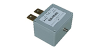
1. Line Impedance Stabilization Network LISN AR 50
|
The LISN AR 50 is used for isolating electric wave in cable bundle test and supply stable impedance for test system; |
|
Max AC 530 V, DC 600 V |
|
|
I rms: 50 A; |
|
|
Frequency Range: 10 kHz ~ 400 MHz. |
|
|
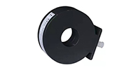
2. Current Coupling Transformer LCT-L5
|
The LCT-L5 is used for coupling current waveforms 1,5A,5B and meet the test requirement of single/multiple stroke (level 1~5) test. |
|
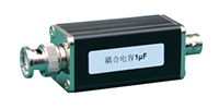
3. External DC Capacitor C33600 / C33500 /C33400
|
The C33600/C33500/C33400 is used together with LISN for conducting cable bundle tests; Maximum DC voltage is 600 V (general configuration is 50 V); |
|
4. Voltage Coupling Transformer LVT-L5B
|
The LVT-L5 is used for coupling voltage waveforms 4, 5A and meet the test requirement of single/multiple stroke (level 1 ~ 5) test. |
|
5. Power Blocking Device CN-1
|
Used to isolate the voltage on the EUT pin from the low source impedance of the signal generator, protecting the signal generator; |
|
Isolation AC maximum voltage 400 V; The maximum voltage of the DC power supply is 600 V; |
|
|
Can meet the power testing requirements for injecting W4, W5A, and W5B waveforms into the pins; |
|
|
6. Transient Blocking Device DN-416T
|
Used to prevent W4, W5A, W5B transient waveforms from damaging the EUT power supply; |
|
AC/power supply maximum voltage 3-phase 400 V 16 A, 0-400 Hz (common mode); DC power supply with a maximum voltage of 600 V 16 A |
|
|
Can meet the power testing requirements for injecting W4, W5A, and W5B waveforms into the pins |
|
|
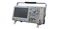
7.Digital Oscilloscope MDO3012 (Tektronix)
|
Frequency 100 MHz; |
|
Sample Rate 1.25 GS/s; |
|
|
Record length 10 Mb. |
|
|
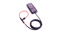
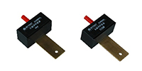
8.Wide-band Current Monitor CWT 150
|
Max. peak current 30 kA; |
|
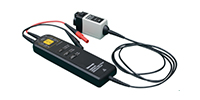
9. Differential Probe THDP0100 (Tektronix)
|
6 kV differential mode, 100 MHz; |
|
The THDP0100 is used for measuring voltage of all waveforms. |
|
|
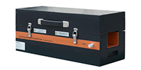
10. Long Pulse Adapter Box ZJH8848L
|
Used for measuring waveforms W1,W4,W5A and W5B. |
|
11. Short Pulse Adapter Box ZJH8848S
|
Used to measure waveform W2. |
|
12. Corelab Software |
The software is used for remote control; |
|
Support connection with oscilloscope for monitoring waveform; |
|
|
Support generating test report. |
|
|
Optional accessories (ETS 160MB) |
|
|
1.Coupling Transformer LVT-2
|
The LVT-2 is used to couple voltage of waveform 2 and waveform 3 (1 MHz & 10 MHz); |
|
It satisfies single stroke, multiple stroke and multiple burst tests of cable bundle;Test level is from 1 to 5; |
|
|
Max. coupling voltage is 2000 V for W2; |
|
|
Max. coupling voltage is 4000 V for W3; |
|
|
2.Coupling Transformer LVT-3
|
The LVT-3 is used to couple current of waveform 6; |
|
It satisfies multiple burst tests of cable bundle; Test level is from 1 to 5; |
|
|
Max. coupling current is 160 A; |
|
|
3.Power Blocking Device CN-2
|
The CN-2 is used to isolate voltages at the pins of the EUT from the low generator impedance in waveform 3 pins direct injection test; |
|
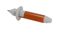
4.Handheld Pin Injection Probe HIP 5000
|
The probe is used in pin injection tests of waveform 3 (1 MHz); |
|
Handheld structure design makes pin injection tests convenient; |
|
|
5.Current Divider MCS 01
|
The MCS 01 is used to measure current of waveforms 2, 3 and 6. |
|
6.Wide-band Current Monitor CM 0103M
|
The CM 0103M is used to measure W2, W3(1 & 10 MHz) and W6; |
|
Max. peak current 5 kA; |
|
|
Sensitivity 0.1 V/A; |
|
|
Frequency: 200 Hz ~ 20 MHz |
|
|
Current time product: 0.2 A·s; |
|
|
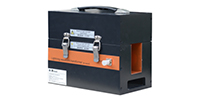
7.35U rack ETS 160MB-35U
|
The ETS 160MB-35U is used to place all
devices and accessories to makes the storage in order; |